오리뎅이의 네떡세상

[오리뎅이의 라우팅 이야기 - 3] Connected - IP 네트워킹, 라우팅의 시작 - 3/3

오리뎅이의 라우팅 테이블 훔쳐보기

안녕하세요? 오리뎅이입니다.


Connected 마지막 편입니다. 인터페이스에 IP와 subnet mask를 설정하면, 라우팅 테이블에 자동으로 ConnectedLocal 엔트리가 생성되었었는데요. 이번에는 Static route 설정으로 connected를 알아 보겠습니다.


Static route로 만드는 Connected

Connected를 만드는 기술 그 두번째입니다. 밑장 빼기 기술 아닙니다. 사기가 아니라는 말씀. (^^), Static route 설정에서 nexthop 또는 gateway를 설정하지 않고, Interface만 지정해서 설정하는 방법으로 Static connected를 만들 수 있습니다. 실제 설정 예를 들어 설명하기에 앞서 각 OS에서 Static route 설정 방법을 확인해 보겠습니다.


Windows 10 static route 
설정
   
예) route add 157.11.5.0 MASK 255.255.255.0  157.55.80.1 METRIC 3 IF 2
             destination^    ^mask                    ^gateway    metric^    ^interface

Linux Static route 설정
예) ip route add 157.11.5.0/24 via 192.168.1.1 dev eth0  metric 1
                destination^             ^gateway         ^ interface  ^metric

                               
Cisco Router Static route 설정

예) ip route 10.1.2.0 255.255.255.0 10.1.1.2  25                 // Old IOS 방식은 nexthop 또는 interface 중 1개만 가능
        destination^          nexthop^           ^AD

    ip route 10.1.2.0 255.255.255.0 Gi0/1  25                     // Old IOS 방식은 nexthop 또는 interface 중 1개만 가능
        destination^          interface^      ^AD                           
    ip route 10.1.2.0 255.255.255.0 Gi0/1 10.1.1.2 25          // New IOS 방식은 nexthop, interface 동시 사용 가능  
        destination^          interface^  nexthop^  ^AD 


Windows 10, Linux는 static route를 설정할 때, destination, nexthop, interface, metric 4가지 파라미터를 사용할 수 있습니다.  Cisco Router는 old IOS에서는 static route 설정 시에 destination, [nexthop/interface], AD(Administrative Distance) 4가지 파라미터를 사용할 수 있지만, nexthop interface, 둘 모두를 동시에 사용할 수는 없습니다. Serial 링크에서는 interface를 사용하고, Ethenet 링크에서는 nexthop을 주로 사용합니다. 그리고, Cisco router는 static route 설정시에는 AD 값은 지정할 수 있지만 metric 값은 설정하지 못합니다. Static route은 metric은 0으로 출력이 되긴 하지만 의미 있는 값이 아니고, 변경이 불가합니다. Dynamic Routing Protocol이 설정하는 metric과 출력 포맷을 동일하게 하기 위해서 routing table을 출력할 때는 [1/0] 과 같이 AD는 1, metric은 0으로 표시가 됩니다. 


Recursive lookup이 일어나지 않도록 하려면?

Nexthop만을 사용하는 경우는 출구 interface를 찾기 위해서 routing table lookup을 한번 더(recursive lookup) 해야합니다. 또한, nexthop만을 지정한 route 엔트리는 interface down과 연결되지 않습니다. Interface down과 연결되지 않는다는 말은 nexthop과 연결된 interface가 down 되더라도 엔트리가 라우팅 테이블에서 삭제되지 않는다는 의미입니다. 반면에 interface를 사용하는 경우에는 인터페이스가 down되면, static route 엔트리가 라우팅 테이블에서 삭제됩니다. 라우터에서는 그리하여 nexthop 사용하기 보다는 interface를 사용하는 것을  더 권장합니다. 최근 Cisco IOS에서는 nexthop interface, 둘 모두를 동시에 사용할 수 있습니다 패킷트레이서는 둘 모두를 동시에 사용할 수 없습니다.


앞 글의 그림5에서 "Destiantion net unreachable" ICMP error 발생 확인을 위해서 각 router들에 가는 길, 오는 길을 static route로 설정을 했었습니다. Static route를 설정할 때, nexthop을 사용하였었습니다. 


1
2
3
4
5
6
7
8
9
10
11
12
13
14
15
16
17
18
19
20
21
22
23
24
25
26
27
28
29
30
 
Router4#sho ip route 
     ... 중략 ... 
     10.0.0.0/8 is variably subnetted, 6 subnets, 3 masks 
C       10.10.10.0/24 is directly connected, GigabitEthernet0/0 
L       10.10.10.1/32 is directly connected, GigabitEthernet0/0 
C       10.10.11.0/30 is directly connected, GigabitEthernet0/1 
L       10.10.11.1/32 is directly connected, GigabitEthernet0/1 
S       10.10.12.0/30 [1/0] via 10.10.11.2 
S       10.10.13.0/24 [1/0] via 10.10.11.2 
 
Router5#show ip route 
     ... 중략 ... 
     10.0.0.0/8 is variably subnetted, 6 subnets, 3 masks 
S       10.10.10.0/24 [1/0] via 10.10.11.1 
C       10.10.11.0/30 is directly connected, GigabitEthernet0/0 
L       10.10.11.2/32 is directly connected, GigabitEthernet0/0 
C       10.10.12.0/30 is directly connected, GigabitEthernet0/1 
L       10.10.12.1/32 is directly connected, GigabitEthernet0/1 
S       10.10.13.0/24 [1/0] via 10.10.12.2 
 
Router6#show ip route 
     ... 중략 ... 
     10.0.0.0/8 is variably subnetted, 6 subnets, 3 masks 
S       10.10.10.0/24 [1/0] via 10.10.12.1 
S       10.10.11.0/30 [1/0] via 10.10.12.1 
C       10.10.12.0/30 is directly connected, GigabitEthernet0/0 
L       10.10.12.2/32 is directly connected, GigabitEthernet0/0 
C       10.10.13.0/24 is directly connected, GigabitEthernet0/1 
L       10.10.13.1/32 is directly connected, GigabitEthernet0/1
cs

참조27 :  그림5의 3개 Router의 라우팅 테이블이 요렇데여~


참조27은 Router4, Router5, Router6의 Routing Table을 보여 줍니다. Connected와 Local 엔트리들 이외에 각 라우터마다 2개의 S 엔트리가 생성되어 있습니다. 이 엔트리들이 Static으로 설정한 static route 엔트리들인데요. 각 엔트리를 보면, via 뒤에 nexthop IP만 있습니다. 출구 Interface가 지정되어 있지 않습니다. 이 경우 어느 interface로 보내야 할 지를 알수 없기 때문에 라우팅 테이블을 한번 더 lookup 해서 출구 인터페이스를 찾게 됩니다. Router4의 경우를 보면, 10.10.13.0/24의 nexthop IP 10.10.11.2는 라우팅 테이블을 한번 더 lookup 하여 10.10.11.0/30 엔트리를 찾습니다. 이제 출구 인터페이스 GigabitEthernet0/1을 찾았습니다. 


Recursive lookup이 일어나지 않도록 하려면, static route 설정할 때, nexthop을 사용하는 대신에 interface를 사용하면 됩니다. 그림5의 환경에서 Router4의 static route 설정을 nexthop에서 interface에서로 모두 변경해 보겠습니다.


1
2
3
4
5
6
7
8
9
10
11
12
13
14
15
16
17
Router4(config)#no ip route 10.10.12.0 255.255.255.252 
Router4(config)#no ip route 10.10.13.0 255.255.255.0 
 
Router4(config)#ip route 10.10.12.0 255.255.255.252 GigabitEthernet 0/1 
%Default route without gateway, if not a point-to-point interface, may impact performance 
Router4(config)#ip route 10.10.13.0 255.255.255.0 GigabitEthernet 0/1 
%Default route without gateway, if not a point-to-point interface, may impact performance 
Router4(config)#exit 
Router4#show ip route 
     ... 중략 ... 
     10.0.0.0/8 is variably subnetted, 6 subnets, 3 masks 
C       10.10.10.0/24 is directly connected, GigabitEthernet0/0 
L       10.10.10.1/32 is directly connected, GigabitEthernet0/0 
C       10.10.11.0/30 is directly connected, GigabitEthernet0/1 
L       10.10.11.1/32 is directly connected, GigabitEthernet0/1 
S       10.10.12.0/30 is directly connected, GigabitEthernet0/1 
S       10.10.13.0/24 is directly connected, GigabitEthernet0/1
cs

참조28 : nexthop을 모두 interface로 바꾸었더니 Connected가 뿅~


nexthop 대신에 interface를 사용하여 static route를 설정하니, 이전에 nexthop IP만 가지고 있던 2개의 Static route가 아래와 같이 directly connected 로 변경되었습니다. 짠~ 하고, connected가 나타났습니다.(^^)


변경 전

S       10.10.12.0/30 [1/0] via 10.10.11.2
S       10.10.13.0/24 [1/0] via 10.10.11.2


변경 후

S       10.10.12.0/30 is directly connected, GigabitEthernet0/1
S       10.10.13.0/24 is directly connected, GigabitEthernet0/1


Static은 Static인데, direct connected 라네요. 그래서 Static route로 만드는 Connected 입니다. 이렇게 변경해도 PC1에서 Server1으로 ping이 될까요? 네~ 물론 됩니다. 되는지 ping 해 봤습니다. (^^)


1
2
3
4
5
6
7
8
9
10
11
12
13
C:\>ping 10.10.13.2 
 
Pinging 10.10.13.2 with 32 bytes of data: 
 
Request timed out. 
Request timed out. 
Request timed out. 
Reply from 10.10.13.2: bytes=32 time<1ms TTL=125 
 
Ping statistics for 10.10.13.2
    Packets: Sent = 4, Received = 1, Lost = 3 (75% loss), 
Approximate round trip times in milli-seconds: 
    Minimum = 0ms, Maximum = 0ms, Average = 0ms
cs

참조29 : Router4에 static route로 connected 만들어 놓고 PC1에서 Server1으로 ping


처음 3번은 "Request timed out."이 발생했어요. "어?? ping 안되는 건가??" 하는 마음이 드는 순간 마지막 4번째 ping이 정상을 찍습니다. 호~~! 이후부터는 계속 정상 ping이 잘 됩니다. 


Connected는 직접 연결 : ARP Request를 직접 destination IP로 보냄

앞에서 계속해서 설명하길 connected는 직접 연결이고, ping 목적지인 host IP로 직접 ARP request를 보내서 ARP reply를 받아서 서로 직접 통신 하는 것이라고 설명을 했었습니다. 그런데, 이게 어쩐일인가요? 10.10.13.2가 Router4에 직접 연결된 host가 아닌데, 도대체 어떻게 된 일입니까요?  맞습니다. connected 라우팅 엔트리는 모든 IP 장비에서 직접 ARP request를 보냅니다. Router4의 ARP table을 확인해 보면, 아래 참조30과 같이 ARP cache table에 10.10.13.2 IP에 대한 MAC learning이 되어 있는 것이 보입니다.


1
2
3
4
5
6
Router4#show ip arp 
Protocol  Address          Age (min)  Hardware Addr   Type   Interface 
Internet  10.10.10.1              -   000C.8506.9701  ARPA   GigabitEthernet0/0 
Internet  10.10.10.2              0   0060.70A6.4230  ARPA   GigabitEthernet0/0 
Internet  10.10.11.1              -   000C.8506.9702  ARPA   GigabitEthernet0/1 
Internet  10.10.13.2              0   0060.47EE.5301  ARPA   GigabitEthernet0/1
cs

참조30 : Router4에 Router6에 직접 연결된 10.10.13.2의 ARP resolution이??? - 니가 여기서 왜 나와?


Static으로 interface만 주고 route를 설정하면, Static connected 엔트리가 생성되고, IP 장비는 해당 엔트리에 직접 ARP Request를 보낼 수 있는 직접 연결된 장비로 인식하여 ARP request를 직접 보냅니다. 이 경우에는 Router5에 proxy ARP 기능이 enable되어 있어서 Router5가 대신 자기 MAC address로 ARP reply를 보내 준 것입니다. 실제 그런지 Router5의 MAC address를 확인해 보겠습니다.


1
2
3
4
5
6
7
Router#show inte GigabitEthernet 0/0
GigabitEthernet0/0 is up, line protocol is up (connected)
  Hardware is CN Gigabit Ethernet, address is 0060.47ee.5301 (bia 0060.47ee.5301)
  Internet address is 10.10.11.2/30
  MTU 1500 bytes, BW 1000000 Kbit, DLY 10 usec,
     reliability 255/255, txload 1/255, rxload 1/255
  ...  후략 ...
cs

참조31 : Router5의 Gi0/0 인터페이스 MAC address is 0060.47ee.5301


Router4는 10.10.13.2가 directly connectd 이기 때문에 ARP Request를 직접 10.10.13.2로 보냈는데, Router5가 대신 자신의 MAC address로 응답을 해 주었던 것입니다. 그렇게 패킷은 Router5에게 전달이 되고, 다시 Router5가 Router6으로 라우팅을 해서 ping 이 정상적으로 동작하게 된 것이었습니다.


connected는 ARP request를 직접 보낸다

라우터에 static route 설정 시 nexthop 대신에 interface 만을 사용하는 것은 recursive lookup을 줄일 수 있다는 면에서는 일면 바람직해 보이지만, ARP request를 직접 보낸다는 점에서 destination host IP 숫자가 제한적인 경우에만 사용하는 것이 좋습니다. 또한, ARP request를 직접 보내므로 destination host가 ARP request를 받아서 응답할 수 있도록 동일 Local Link에 존재하거나, Router가 proxy ARP로 ARP request에 대리 응답을 해 줄 수 있는 환경이어야만 합니다.


예를 들어 default route(0.0.0.0)를 interface 만을 이용해서 stratic route로 설정한 경우를 생각해 보면, 모든 destination에서 직접 ARP request를 보냅니다. 라우터가 proxy ARP로 응답을 해주는 상황이라면, 라우팅할 패킷이 발생하는 destination IP 수 만큼 ARP cache table entry도 등록이 될 것입니다. Destination IP가 많아지면, 성능저하를 가져 올 수도 있고 ARP cache table 메모리가 부족해 질 수도 있을 것입니다.


최근 라우터들은 기본적으로 nexthop과 interface를 동시에 지정할 수 있으니 특별한 경우가 아니라면 static route 설정 시 interface만을 사용하는 것은 지양하는 게 좋습니다. 특별한 경우는 어떠한 경우가 있을까요?  하나의 LAN에서 서로 다른 subnet 대역 IP를 가진 host가 서로 통신이 되어야 하는 경우가 그런 특별한 경우가 될 수 있을텐데요.  하나의 LAN에서 서로 다른 subnet 대역의 IP는 라우터를 통해야지만 통신이 된다고 배웠었는데, 이게 정말 될까요?  


그림8. 동일 LAB에서 서로 다른 subnet끼리 통신이 된다고요?

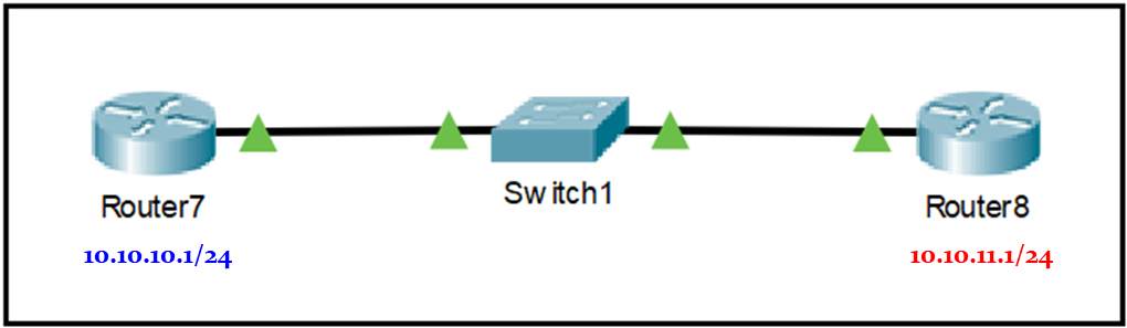
패킷트레이서에서 하나의 스위치에 연결된 서로 다른 subnet 대역끼리 static route로 서로 통신이 되는지 확인해 보기 위해서 그림8과 같이 구성하고, IP와 subnet mask, 그리고 static route를 각각 설정하였습니다. 


1
2
3
4
5
6
7
8
9
10
11
12
13
14
15
16
17
18
19
20
21
22
23
24
25
26
27
28
29
30
31
32
33
34
35
36
37
38
39
40
41
42
43
44
45
46
47
48
49
50
51
52
53
Router7#show ip route
     ... 중략 ...
     10.0.0.0/8 is variably subnetted, 2 subnets, 2 masks
C       10.10.10.0/24 is directly connected, GigabitEthernet0/0
L       10.10.10.1/32 is directly connected, GigabitEthernet0/0
 
Router7(config)#ip route 10.10.11.0 255.255.255.0 gigabitEthernet 0/0
%Default route without gateway, if not a point-to-point interface, may impact performance
Router7#show ip route
     ... 중략 ...
     10.0.0.0/8 is variably subnetted, 3 subnets, 2 masks
C       10.10.10.0/24 is directly connected, GigabitEthernet0/0
L       10.10.10.1/32 is directly connected, GigabitEthernet0/0
S       10.10.11.0/24 is directly connected, GigabitEthernet0/0
 
Router7#ping 10.10.11.1
 
Type escape sequence to abort.
Sending 5100-byte ICMP Echos to 10.10.11.1, timeout is 2 seconds:
.....
Success rate is 0 percent (0/5)
 
Router7#show ip arp
Protocol  Address          Age (min)  Hardware Addr   Type   Interface
Internet  10.10.10.1              -   0007.EC52.8801  ARPA   GigabitEthernet0/0
 
---------------------------------------------------------------------------------------------
 
Router8#show ip route
     ... 중략 ...
     10.0.0.0/8 is variably subnetted, 2 subnets, 2 masks
C       10.10.11.0/24 is directly connected, GigabitEthernet0/0
L       10.10.11.1/32 is directly connected, GigabitEthernet0/0
 
Router8(config)#ip route 10.10.10.0 255.255.255.0 gigabitEthernet 0/0
%Default route without gateway, if not a point-to-point interface, may impact performance
Router8#show ip route
     ... 중략 ...
     10.0.0.0/8 is variably subnetted, 3 subnets, 2 masks
C       10.10.11.0/24 is directly connected, GigabitEthernet0/0
L       10.10.11.1/32 is directly connected, GigabitEthernet0/0
S       10.10.10.0/24 is directly connected, GigabitEthernet0/0
 
Router8#ping 10.10.10.1
 
Type escape sequence to abort.
Sending 5100-byte ICMP Echos to 10.10.10.1, timeout is 2 seconds:
.....
Success rate is 0 percent (0/5)
 
Router8#show ip arp
Protocol  Address          Age (min)  Hardware Addr   Type   Interface
Internet  10.10.11.1              -   0030.F20C.DE01  ARPA GigabitEthernet0/0
cs

참조32 : Static connected로 서로 다른 subnet 대역간 ping이 될까요? - 패킷트레이스는 안되네요


패킷트레이서에서는 설정은 잘 들어가 지지만, 실제로 ping은 안되는군요. 되도록 구현을 안한 것 같습니다. Virtual Box Linux VM을 이용해서 linux box 실제 상황에서는 되는지 확인해 봤습니다. 


1
2
3
4
5
6
7
8
9
10
11
12
13
14
15
16
17
18
19
20
21
22
23
24
25
26
27
28
29
30
31
32
33
34
35
36
37
38
39
limcs@limcs-VM10:~/Desktop$ ifconfig enp0s9
enp0s9: flags=4163<UP,BROADCAST,RUNNING,MULTICAST>  mtu 1500
        inet 172.16.10.11  netmask 255.255.255.0  broadcast 0.0.0.0
        ether 08:00:27:b9:6f:ff  txqueuelen 1000  (Ethernet)
        ... 후략 ...
 
limcs@limcs-VM10:~/Desktop$ route -n
Kernel IP routing table
Destination     Gateway         Genmask         Flags Metric Ref    Use Iface
0.0.0.0         10.0.2.2        0.0.0.0         UG    100    0        0 enp0s3
172.16.10.0     0.0.0.0         255.255.255.0   U     0      0        0 enp0s9
limcs@limcs-VM10:~/Desktop$ sudo ip route add 172.16.11.0/24 dev enp0s9
limcs@limcs-VM10:~/Desktop$ route -n
Kernel IP routing table
Destination     Gateway         Genmask         Flags Metric Ref    Use Iface
0.0.0.0         10.0.2.2        0.0.0.0         UG    100    0        0 enp0s3
172.16.10.0     0.0.0.0         255.255.255.0   U     0      0        0 enp0s9
172.16.11.0     0.0.0.0         255.255.255.0   U     0      0        0 enp0s9
 
---------------------------------------------------------------------------------------------
 
limcs@limcs-VM11:~/Desktop$ ifconfig enp0s9
enp0s9: flags=4163<UP,BROADCAST,RUNNING,MULTICAST>  mtu 1500
        inet 172.16.11.11  netmask 255.255.255.0  broadcast 0.0.0.0
        ether 08:00:27:e1:df:51  txqueuelen 1000  (Ethernet)
        ... 후략 ...
 
limcs@limcs-VM11:~/Desktop$ route -n
Kernel IP routing table
Destination     Gateway         Genmask         Flags Metric Ref    Use Iface
0.0.0.0         10.0.2.2        0.0.0.0         UG    100    0        0 enp0s3
172.16.11.0     0.0.0.0         255.255.255.0   U     0      0        0 enp0s9
limcs@limcs-VM11:~/Desktop$ sudo ip route add 172.16.10.0/24 dev enp0s9
limcs@limcs-VM11:~/Desktop$ route -n
Kernel IP routing table
Destination     Gateway         Genmask         Flags Metric Ref    Use Iface
0.0.0.0         10.0.2.2        0.0.0.0         UG    100    0        0 enp0s3
172.16.10.0     0.0.0.0         255.255.255.0   U     0      0        0 enp0s9
172.16.11.0     0.0.0.0         255.255.255.0   U     0      0        0 enp0s9
cs

참조33 : Linux machine에 각각 172.16.10.11/24, 172.16.11.11/24 로 다른 subnet 대역 IP 할당했씨유~


참조33과 같이 2개의 VM이 L2 bridge로 연결되어 있는 상황에서 한쪽에는 172.16.10.11/24, 다른 한쪽에는 172.16.11.11/24로인터페이스 IP를 각각 설정하였습니다. 그런 후에 서로 간에 상대방 IP에 대해서 Static Router 설정을 Interface만 주도록 설정해서 Connected 라우팅 엔트리가 등록 되게 만들었습니다.  Subnet이 다른데도 실제 ARP request가 나가고, ARP reply 응답을 해서 ICMP ping packet을 서로 주고 받게 되는지 확인하기 위해서 양쪽 host에 tcpdump를 걸어서 확인했습니다.


1
2
3
4
5
6
7
8
9
10
11
12
13
14
15
16
17
18
19
20
21
22
23
24
limcs@limcs-VM10:~$ ping 172.16.11.11 -1
PING 172.16.11.11 (172.16.11.1156(84) bytes of data.
64 bytes from 172.16.11.11: icmp_seq=1 ttl=64 time=0.830 ms
 
--- 172.16.11.11 ping statistics ---
1 packets transmitted, 1 received, 0% packet loss, time 0ms
rtt min/avg/max/mdev = 0.830/0.830/0.830/0.000 ms
 
limcs@limcs-VM10:~/Desktop$ sudo tcpdump -i enp0s9 -n host 172.16.11.11
tcpdump: verbose output suppressed, use -v or -vv for full protocol decode
listening on enp0s9, link-type EN10MB (Ethernet), capture size 262144 bytes
 
20:11:56.814760 ARP, Request who-has 172.16.11.11 tell 172.16.10.11, length 28
20:11:56.815190 ARP, Reply 172.16.11.11 is-at 08:00:27:e1:df:51, length 46
20:11:56.815200 IP 172.16.10.11 > 172.16.11.11: ICMP echo request, id 1, seq 1, length 64
20:11:56.815516 IP 172.16.11.11 > 172.16.10.11: ICMP echo reply, id 1, seq 1, length 64
 
limcs@limcs-VM10:~$ arp 172.16.11.11
Address                  HWtype  HWaddress           Flags Mask            Iface
172.16.11.11             ether   08:00:27:e1:df:51   C                     enp0s9
 
limcs@limcs-VM11:~$ sudo arp 172.16.10.11
Address                  HWtype  HWaddress           Flags Mask            Iface
172.16.10.11             ether   08:00:27:b9:6f:ff   C                     enp0s9
cs

참조34 : ping 잘 되고, arp request/reply 잘 주고 받고, arp cache table도 잘 만들어 지네요


VirtualBox로 구성하였지만, 그림8과 같은 구성인데, 서로 다른 대역의 host끼리 L2 스위치를 통해서 서로 직접 통신이 잘 되는 것을 확인하였습니다.


IPv6에서는 Static connected로 서로 다른 대역 통신 X

Static connected로 만들었기 때문에 ARP request를 직접 보내는 것은 이해가 되지만, proxyARP도 아닌데 상대 host는 다른 subnet 대역에서 온 ARP request에 대해서 응답을 해 주네요. 이것은 IPv4 ARP 프로토콜이 IP 헤더가 없는 Link Layer protocol이기 때문에 ARP reply할 때, 동일 subnet 여부를 체크하지 않기 때문입니다. IPv6에서는 Neighbor Discovery 프로토콜이 ARP 프로토콜을 대체하였습니다. 그런데, 이 Neighbor Discovery 프로토콜은 ICMPv6로 동작하기 때문에 L3 Layer에서 동작합니다. 그래서 Neighb Discovery 요청(Neighbor Solicitation)에 대한 응답(Negibhbor Advertisement)는 동일 subnet에서 보낸 요청에만 응답을 하도록 되어 있습니다. 그렇기 때문에 IPv4 Static Connected처럼 서로 다른 대역의 IP가 서로 통신이 이루어지지 않습니다. 


Windows는 Static connected를 설정하는 방법이 Router, Linux와는 다릅니다. Windows에서는 nexthop을 안주는 게 아니고, nexthop을 자기 자신 IP를 주거나 0.0.0.0 으로 해서 interface와 함께 설정을 하면 됩니다.


1
2
3
4
5
6
7
8
9
10
11
12
13
14
15
16
17
18
19
20
21
22
23
24
25
26
C:\WINDOWS\system32>route add 11.12.13.0 mask 255.255.255.0 192.168.35.120 IF 9
 확인!
 
C:\WINDOWS\system32>route add 12.13.14.0 mask 255.255.255.0 0.0.0.0 IF 9
 확인!
 
C:\WINDOWS\system32>route print
===========================================================================
인터페이스 목록
 13...00 05 9a 3c 7a 00 ......Cisco AnyConnect Secure Mobility Client Virtual Miniport Adapter for Windows x64
  9...b8 ac 6f 1d 1e 36 ......Intel(R) 82567LM-3 Gigabit Network Connection
 10...0a 00 27 00 00 0a ......VirtualBox Host-Only Ethernet Adapter
  1...........................Software Loopback Interface 1
===========================================================================
 
IPv4 경로 테이블
===========================================================================
활성 경로:
네트워크 대상         네트워크 마스크      게이트웨이         인터페이스    메트릭
          0.0.0.0          0.0.0.0       192.168.35.1   192.168.35.120     25
       11.12.13.0    255.255.255.0             연결됨    192.168.35.120     26
     11.12.13.255  255.255.255.255             연결됨    192.168.35.120    281
       12.13.14.0    255.255.255.0             연결됨    192.168.35.120     26
     12.13.14.255  255.255.255.255             연결됨    192.168.35.120    281
        127.0.0.0        255.0.0.0             연결됨         127.0.0.1    331
        127.0.0.1  255.255.255.255             연결됨         127.0.0.1    331
cs

참조35 : Windows10에서 Static route로 "연결됨" 라우팅 엔트리 만들기


참조 35와 같이 Windows에서는 static route 설정 시 gateway를 자기 자신 IP로 하거나(11.12.13.0), 0.0.0.0을 주거나(12.13.14.0) 모두 connected(연결됨) 엔트리가 만들어 지는 것을 볼 수 있습니다.


Connected를 단편으로 정리하려고 하다 보니, 글이 투머치 롱롱 스토리에 가독성도 떨어지는 것 같고 해서 글을 3편으로 분리하였습니다. ^^


오리뎅이의 라우팅 이야기는 Connected, Static Route, RIP, OSPF, IS-IS, iBGP, eBGP, VRF Lite, VRF(MPLS L3 VPN), VxLAN, EVPN까지 쭈욱 이어질 예정입니다. 함께 쭈욱 같이 공부해 보시죠. 


긴 글 끝까지 읽어 주셔서 고맙습니다. 


 2020년 12월 6일 일요일 저녁 수원에서 뒤뚱뒤뚱~~~~  [오리]


[오리뎅이의 라우팅 이야기 - 1] Connected - IP 네트워킹, 라우팅의 시작 - 1/3

오리뎅이의 라우팅 테이블 훔쳐보기

안녕하세요? 오리뎅이입니다.


티스토리에 새롭게 둥지를 만들고, 첫번째 글을 작성하고 있습니다. 작년(2019년) 중반 즈음에 쿠버네티스를 접하게 되면서, 연이어 Public Cloud까지 공부해야 할 것들이 너무 많아서 이것 저것 들여다 본다고, 블로그 글을 거의 올리지 못하고 있었습니다. 계속 주어 담기만 하다보니, 하고픈 이야기들이 꽉꽉 들어 차서 흘러 넘칠 것 같습니다. 이제 이야기 보따리를 좀 풀어 보려고 합니다. (^^). 그 첫번째로 라우팅 프로토콜 이야기 보따리를 풀어 헤쳐 보겠습니다.


[오리뎅이의 LAN 통신 이야기]에서는 주로 LAN Switching에 대해서 다루었었습니다. 동일한 LAN 내부에 있는 목적지 장비와의 통신 과정, 그리고 하나의 LAN에 속해 있는 장비와 다른 LAN에 속해 있는 장비와의 통신 과정을 삼테이블(Routing Table, ARP Table, MAC Table)의 생성과 변경 그리고 삭제 과정을 통해서 살펴 보았었습니다. 고로 LAN과 다른 LAN간의 통신은 Router 혹은 Routing 기능을 제공하는 L3 이상 장비를 통해서 이루어 진다는 것을 저희는 LAN 통신 이야기에서 이미 알아 보았었습니다.  그렇지만, LAN 통신 이야기에서는 라우팅 프로토콜들에 대해서는 다루지 않았었습니다.


LAN 통신 이야기에 이어서 라우팅 프로토콜에 대한 글을 계속하려는 생각이 없었던 것은 아니었지만, 저 개인적으로는 당시에 라우팅 프로토콜을 Deep Dive 해야 할 필요성을 느끼지 못했었기 때문에 미루고 있었습니다. 그런데, 쿠버네티스와 퍼블릭 클라우드를 공부하면서 오히려 전에는 사용할 일이 없겠다고 느꼈던 라우팅 프로토콜, BGP의 어택(?)을 받았습니다. 또한 VxLAN(Virtual eXtensible LAN)EVPN(Ethernet VPN)을 기반으로 해서 Leaf/Spine switch로 구성되는 Data Center IP Fabric에서도 Underlay IGPOverlay iBGP, 그리고 Customer tenant network와의 eBGP 연동 등으로 동적(Dynamic) Routing Protocol을 업무에서 접하게 되는 빈도가 전에 없이 급증 하였습니다. BGP를 자세하게 이해하지 않고서는 EVPN을 이해할 수 없습니다. 또한, BGP를 이해하려면 IGP로 사용되는 OSPF나 IS-IS에 대해서도 자세하게 알아야 할 필요가 있습니다. 결국 모 다 알아야 되는거 아니겠습니꽈? (^^). 지금 만나러 갑니다. 다 주거써~ 라우팅 프로토콜들!! 딱 기다렷!!


경고1 : 이 글은 네트워크 입문자분들을 독자로 예상하고 쓰는 글이오니, 중수 이상 분들은 오글거림을 각오하삼!!

경고2 : 글 내용이 투머치 롱롱 하니께유, 심호흡 한번씩 하시고 시작하세유~~


Connected - IP 네트워킹, 라우팅의 시작

일반적으로 잘 알려진 동적(Dynamic) 라우팅 프로토콜들로는 RIP, OSPF, IS-IS, BGP(iBGP, eBGP)가 있습니다. 그 외에 시스코에서 만든 IGRP와 EIGRP도 시스코 장비의 시장 장악력에 기반하여 많이 사용되고 있기때문에, 일반 IT 엔지니어들에게는 몰라도 스위치나 라우터 같은 네트워크 장비를 다루는 네트워크 엔지니어들에게는 잘 알려져 있습니다.  다이나믹 라우팅 프로토콜과 더불어 모든 IP 장비의 라우팅 테이블에 빠지지 않는 두가지 라우팅 프로토콜이 있습니다. 바로 ConnectedStatic Routing입니다. Cisco 라우터에서는 Connected와 Static Routing도 각각의 하나의 라우팅 프로토콜 프로세스로 구동을 한다고 합니다. 다른 벤더 장비에서도 그렇게 동작하는지는 모르겠습니다. 동적 라우팅 프로토콜들에 대해서 자세하게 알아보기 이전에 ConnectedStatic Routing에 대해 자세히 알아 보려고 합니다. 지금, Now, 당장은 우선  Connected (연결됨)에 대해 자세히 알아 볼 것입니다.  Connected 하면 떠올려야 할 아래 몇가지 중요한 개념들에 대해서 하나씩 하나씩 자세히 알아 볼 것입니다.  


    - Connected를 만드는 기술

      1) 인터페이스에 IP와 subnet mask를 설정하는 순간 - Connected의 탄생

      2) Static route로 만드는 Connected

    - L2 연결은 MAC으로 통신한다는 의미가 아니랍니다

    - 직접 전달 vs 간접 전달

    - 라우터의 직접 전달

    - Connected가 라우팅 테이블에서 사라졌다 - 링크 down

    - "Destination host unreachable" vs "Destination net unreachable"


Winodws, Linux 및 라우터에서 각각 라우팅 테이블을 출력해 보면, 라우팅 테이블 엔트리(entry:항목)에서 Connected (연결됨)를 쉽게 발견할 수 있습니다. 아래 참조1, 참조2, 참조3은 각각 Windows 10, Cisco Router, Ubuntu Linux에서 라우팅 테이블을 출력해 본 예입니다.


1
2
3
4
5
6
7
8
9
10
11
12
C:\WINDOWS\system32>route print
 
===========================================================================
IPv4 경로 테이블
===========================================================================
활성 경로:
네트워크 대상     네트워크 마스크         게이트웨이   인터페이스     메트릭
       0.0.0.0          0.0.0.0       192.168.35.1    192.168.35.120     25
  192.168.35.0    255.255.255.0             연결됨    192.168.35.120    281
192.168.35.120  255.255.255.255             연결됨    192.168.35.120    281
192.168.35.255  255.255.255.255             연결됨    192.168.35.120    281
===========================================================================
cs

참조1 : Windows 10 라우팅 테이블


Windows 라우팅 테이블에서는 한글인 경우에는 게이트웨이 컬럼에 연결됨으로 표시가 됩니다. 영문 윈도우인 경우에는 Connected 라고 출력이 됩니다.


1
2
3
4
5
6
7
8
9
10
11
12
Router# show ip route 
Codes: C - connected, S - static, I - IGRP, R - RIP, M - mobile, B - BGP
       D - EIGRP, EX - EIGRP external, O - OSPF, IA - OSPF inter area 
       E1 - OSPF external type 1, E2 - OSPF external type 2, E - EGP
       i - IS-IS, L1 - IS-IS level-1, L2 - IS-IS level-2* - candidate default
 
Gateway of last resort is not set
 
C       172.19.64.0 is directly connected, Ethernet0
     171.69.0.0 is variably subnetted, 2 subnets, 2 masks
C       171.69.232.32 255.255.255.240 is directly connected, Ethernet0
S       171.69.0.0 255.255.0.0 is directly connected, Ethernet0
cs

참조2 : Cisco Router 라우팅 테이블


Cisco 라우터의 라우팅 테이블에서는 "show ip route" 명령으로 라우팅 테이블 엔트리(항목)를 조회할 수 있습니다. 참고2를 보면, 윗 부분에 Codes 들에 대한 설명이 쭈르륵 나열되어 있습니다. 그 중에 가장 첫번째에 "C - connected" 라고 보여주고 있습니다. 또한 중간 부분에는 "directly connected, Ethernet0"와 같이 어느 인터페이스에 직접 연결되어 있는지도 설명해 주고 있습니다. 밑부분에 엔트리들을 보면, 맨 앞에 C, S 와 같이 영문 대문자로 각 엔트리가 어떤 라우팅 프로토콜에 의해서 등록된 것인지를 표시해 보여 줍니다. S는 static routing protocol에 의해서 설정된 것임을 나타냅니다. 


* 엔트리(entry:항목) : 라우팅 테이블을 출력하면, 많은 행(row)들이 출력됩니다. 행 하나 하나를 엔트리라고 부릅니다


1
2
3
4
5
6
7
8
9
10
root@k1-master01:~# route -n
Kernel IP routing table
Destination     Gateway         Genmask         Flags Metric Ref    Use Iface
0.0.0.0         172.28.1.1      0.0.0.0         UG    0      0        0 ens1f0
10.244.24.64    172.19.21.13    255.255.255.192 UG    0      0        0 tunl0
10.244.108.0    0.0.0.0         255.255.255.192 U     0      0        0 *
10.244.108.10   0.0.0.0         255.255.255.255 UH    0      0        0 vethcbcf231e16d
10.244.108.11   0.0.0.0         255.255.255.255 UH    0      0        0 veth039a14621a0
172.17.0.0      0.0.0.0         255.255.0.0     U     0      0        0 docker0
172.18.1.0      0.0.0.0         255.255.255.0   U     0      0        0 ens1f0
cs

참조3 : Linux 라우팅 테이블 by "route -n"


Linux에서는 "route -n" 명령으로 라우팅 테이블을 출력해 볼 수 있습니다. Gateway column이  "0.0.0.0" 으로 표시되는 것들이 Connected 입니다. Linux에서는 "route -n" 명령 외에 "ip route show" 명령을 이용해서도 라우팅 테이블 항목들을 아래와 같이 출력해 볼 수 있습니다. 


1
2
3
4
5
6
7
8
9
root@k1-master01:~# ip route show
default via 172.18.1.1 dev ens1f0 proto static
10.244.24.64/26 via 172.19.21.13 dev tunl0 proto bird onlink
blackhole 10.244.108.0/26 proto bird
10.244.108.10 dev vethcbcf231e16d scope link
10.244.108.11 dev veth039a14621a0 scope link
10.244.112.192/26 via 172.19.21.11 dev tunl0 proto bird onlink
172.17.0.0/16 dev docker0 proto kernel scope link src 172.17.0.1 linkdown
172.18.1.0/24 dev ens1f0 proto kernel scope link src 172.18.1.24
cs

참조4 : Linux 라우팅 테이블 by "ip route show"


"route -n" 명령의 출력문에서 Gateway가 "0.0.0.0" 이었던 destination network에는 공통적으로 "scope link"가 적혀 있습니다. Linux에서 "man ip" 명령으로 scope에 대한 설명을 보면, scope 에 대해서 아래와 같이 설명하고 있습니다.


1
2
3
4
scope SCOPE_VAL
 the scope of the destinations covered by the route prefix.  SCOPE_VAL may be a number or a string from 
 the file/etc/iproute2/rt_scopes.  If this parameter is omitted, ip assumes scope global for all gatewayed 
 unicast routes,scope link for direct unicast and broadcast routes and scope host for local routes.
cs

참조5 : Linux "man ip route" 명령으로 조회한 scope link 정의


"scope link for direct unicast and broadcast routes" : 직접 연결된 unicast와 broadcast 루트


이렇게 모든 IP 장비의 라우팅 테이블에는 무조건 Connected 항목이 있습니다. 이 항목이 없다면 거짓말입니다. "무조건 무조건이야~~~!"  왜 무조건일까요? 어떻게 Connected가 생성되는지를 알게 되면, 왜 무조건인지 이해가 됩니다. 함께 알아 보시죠~!  ^^


Connected를 만드는 기술

Connected를 만드는 방법은 다음과 같이 2가지가 있습니다. 첫번째 방법은 IP 월드를 살고 있는 저희들이 너무나 잘 알고 있는 방법입니다. 


    1) 인터페이스에 IP와 subnet을 설정하는 방법

    2) Static route 설정 시 nexthop 지정하지 않고, interface만 지정하는 방법


PC나 노트북을 받아서 Interface에 IP와 subnet을 그리고 Gateway를 설정하는 것은 누구나가 알고 있습니다. PC나 서버와 같은 host 뿐만 아니라 라우터와 L4/L7 Load Balancer, Firewall, NAT, 스마트폰에 이르기까지 모든 IP 통신을 하는 장비들은 Ethernet Interface에 IP와 subnet을 설정하면, 라우팅 테이블에 connected route 엔트리가 생성 됩니다. 시스코 패킷 트레이스를 이용해서 라우터와 PC, 그리고 서버에 각각 IP와 subnet을 설정해서 connected가 생성되는지를 확인해 보겠습니다. 먼저 라우터와 라우터간 연결 인터페이스에 IP와 subnet을 설정해서 connected route 엔트리가 생성되는지를 보겠습니다.


인터페이스에 IP와 subnet을 설정하는 방법 - 라우터


그림1. 라우터와 라우터 연결

패킷트레이서에서 2911 IP 2대를 서로 연결하고, IP와 subnet은 설정하지 않은 상태에서 route table을 보면 아래 참조5와 같이 아무런 엔트리도 생성되어 있지 않습니다.


1
2
3
4
5
6
7
8
9
10
11
12
Router#show ip route
Codes: L - local, C - connected, S - static, R - RIP, M - mobile, B - BGP
       D - EIGRP, EX - EIGRP external, O - OSPF, IA - OSPF inter area
       N1 - OSPF NSSA external type 1, N2 - OSPF NSSA external type 2
       E1 - OSPF external type 1, E2 - OSPF external type 2, E - EGP
       i - IS-IS, L1 - IS-IS level-1, L2 - IS-IS level-2, ia - IS-IS inter area
       * - candidate default, U - per-user static route, o - ODR
       P - periodic downloaded static route
 
Gateway of last resort is not set
 
Router#
cs

참조6 : 인터페이스에 IP와 subnet을 설정하기 전 라우팅 테이블


이제 양쪽 라우터끼리 서로 연결된 인터페이스에 각각 IP와 subnet을 설정하고, connected route 엔트리가 생성되는 것을 확인해 보겠습니다.


1
2
3
4
5
6
7
8
9
10
11
12
13
14
15
16
17
18
19
20
21
22
23
24
25
26
27
28
29
30
31
32
33
34
35
36
37
38
39
40
41
42
43
44
45
46
47
48
49
50
51
52
53
54
55
56
57
58
59
60
61
62
63
64
65
Router2#conf t
Enter configuration commands, one per line.  End with CNTL/Z.
Router2(config)#int GigabitEthernet 0/0
Router2(config-if)#ip address 10.10.10.1 255.255.255.252
Router2(config-if)#no shut
%LINK-5-CHANGED: Interface GigabitEthernet0/0, changed state to up
Router2(config-if)#exit
%LINEPROTO-5-UPDOWN: Line protocol on Interface GigabitEthernet0/0, changed state to up
Router2>show ip route
Codes: L - local, C - connected, S - static, R - RIP, M - mobile, B - BGP
       D - EIGRP, EX - EIGRP external, O - OSPF, IA - OSPF inter area
       N1 - OSPF NSSA external type 1, N2 - OSPF NSSA external type 2
       E1 - OSPF external type 1, E2 - OSPF external type 2, E - EGP
       i - IS-IS, L1 - IS-IS level-1, L2 - IS-IS level-2, ia - IS-IS inter area
       * - candidate default, U - per-user static route, o - ODR
       P - periodic downloaded static route
 
Gateway of last resort is not set
 
     10.0.0.0/8 is variably subnetted, 2 subnets, 2 masks
C       10.10.10.0/30 is directly connected, GigabitEthernet0/0
L       10.10.10.1/32 is directly connected, GigabitEthernet0/0
 
Router2>ping 10.10.10.2
 
Type escape sequence to abort.
Sending 5100-byte ICMP Echos to 10.10.10.2, timeout is 2 seconds:
.!!!!
Success rate is 80 percent (4/5), round-trip min/avg/max = 0/0/0 ms
 
Router2>
 
----------------------------------------------------------------------------------------
 
Router3#conf t
Enter configuration commands, one per line.  End with CNTL/Z.
Router3(config)#int GigabitEthernet 0/0
Router3(config-if)#ip address 10.10.10.2 255.255.255.252
Router3(config-if)#no shut
%LINK-5-CHANGED: Interface GigabitEthernet0/0, changed state to up
%LINEPROTO-5-UPDOWN: Line protocol on Interface GigabitEthernet0/0, changed state to up
Router3(config-if)#exit
Router3#show ip route
Codes: L - local, C - connected, S - static, R - RIP, M - mobile, B - BGP
       D - EIGRP, EX - EIGRP external, O - OSPF, IA - OSPF inter area
       N1 - OSPF NSSA external type 1, N2 - OSPF NSSA external type 2
       E1 - OSPF external type 1, E2 - OSPF external type 2, E - EGP
       i - IS-IS, L1 - IS-IS level-1, L2 - IS-IS level-2, ia - IS-IS inter area
       * - candidate default, U - per-user static route, o - ODR
       P - periodic downloaded static route
 
Gateway of last resort is not set
 
     10.0.0.0/8 is variably subnetted, 2 subnets, 2 masks
C       10.10.10.0/30 is directly connected, GigabitEthernet0/0
L       10.10.10.2/32 is directly connected, GigabitEthernet0/0
 
Router3>ping 10.10.10.1
 
Type escape sequence to abort.
Sending 5100-byte ICMP Echos to 10.10.10.1, timeout is 2 seconds:
!!!!!
Success rate is 100 percent (5/5), round-trip min/avg/max = 0/0/1 ms
 
Router3>
cs

참조7 : 라우터 인터페이스에 IP와 subnet 설정하니 뚝딱 생겨난 Connected와 Local


Router2와 Router3가 서로 연결된 GigabitEthernet 0/0 인터페이스에 각각 IP와 subnet mask를 입력하고, "no shut" 명령을 입력하자,


"line protocol %LINEPROTO-5-PDOWN: Line protocol on Interface GigabitEthernet0/0, changed state to up"


이와 같은 로그가 출력되었고, 이어서 바로 라우팅 테이블을 다시 확인해 보니, 2개의 routing 엔트리가 생성되어 있는 것이 보입니다.


"어! 왜 2개지??? ㅎㅎㅎ"


앞에 "C" 로 마킹된 것은 제가 지금까지 얘기하고 있었던 "Connected"인데요. "L" 로 마킹 된 엔트리가 하나 더 생성되어 있네요.  L은 위에 설명을 보니 "L - local" 이라고 되어 있습니다. 그리고, 엔트리의 IP/prefix를 보니 10.10.10.1/32와 10.10.10.2/32 로 자기 자신 Interface에 할당 된 IP가 host subnet(subnet mask 255.255.255.255 또는 Prefix length 32)으로 local로 생성이 되는군요. 당황스럽네요. 다행히 사업자에게 데모하는 상황이 아니라 당황한 얼굴 표정은 안 들켰습니다. (^^)  사업자에 데모하는 와중에 예상치 못한 이런 결과가 톡 튀어 나오면, 정말 당황 스럽죠. 당황해서 "어버버~~~" 하기도 합니다. ㅋㅋㅋ


Local은 라우터에서나 Host에서나 같은 의미로 사용됩니다. Linux에서도 아래와 같이 "ip route show table local" 이라는 명령으로 host inteface에 항당한 IP들이 local routing table에 설정되어 있는 것을 확인할 수 있습니다.


1
2
3
4
root@k1-master01:~# ip route show table local
local 127.0.0.1 dev lo proto kernel scope host src 127.0.0.1
local 172.28.1.24 dev enp1s0 proto kernel scope host src 172.28.1.24
local 172.29.21.6 dev enp6s0 proto kernel scope host src 172.29.21.6
cs

참조8 : Linux host local routing table


참고로 쿠버네티스의 Serivce Type의 하나인 nodePort 서비스 타입을 설명하는 내용 중에 "nodePort 타입 서비스를 생성하면 LocalIP:NodePort로 서비스에 접속이 가능하다"는 설명이 있습니다. 여기서 말하는  LocalIP도 linux host에 설정된 Local IP들을 의미합니다. NodePort 서비스 접속은 loopback IP인 localhost, 127.0.0.1을 포함한 모든 host Local IP를 사용할 수 있습니다.


Windows도 Local을 라우팅 테이블에 등록합니다. 저희가 무심코 지나쳤지만, 2번째, 3번째, 4번째 엔트리를 한번 보실까요. 2번째 엔트리가 Connected subnet입니다. 3번째 엔트리가 바로 Local 이네요. 4번째 엔트리는 subnet broadcast IP이군요.


192.168.35.0     255.255.255.0                연결됨    192.168.35.120    281    // 2번째 엔트리,  Connected
192.168.35.120  255.255.255.255             연결됨    192.168.35.120    281    // 3번째 엔트리,  Local
192.168.35.255  255.255.255.255             연결됨    192.168.35.120    281    // 4번째 엔트리,  Broadcast


인터페이스에 IP와 subnet을 설정하는 방법 - 리눅스

잠시 이야기가 삼천포에 들렀다 왔습니다. 다시, 제자리로 돌아와서 Linux에서 서로 직결된 Interface에 IP와 subnet을 설정하여 connected route entry(Gateway가 0.0.0.0 인 엔트리)가 생성되는 것을 살펴 보겠습니다. Virtual Box를 이용해서 Ubuntu 20.04 VM 2개를 띄워서 만들어 봤습니다. Test를 위해서 내부네트워크 어답터 1개씩을 2개 VM에 각각 추가하였습니다.


1
2
3
4
5
6
7
8
9
10
11
12
13
14
15
16
17
limcs@limcs-VirtualBox:~$ ifconfig enp0s9
enp0s9: flags=4163<UP,BROADCAST,RUNNING,MULTICAST>  mtu 1500
        inet6 fe80::6a0e:3c89:e832:4984  prefixlen 64  scopeid 0x20<link>
        ether 08:00:27:b9:6f:ff  txqueuelen 1000  (Ethernet)
        RX packets 286  bytes 67164 (67.1 KB)
        RX errors 0  dropped 0  overruns 0  frame 0
        TX packets 660  bytes 106522 (106.5 KB)
        TX errors 0  dropped 0 overruns 0  carrier 0  collisions 0
 
limcs@limcs-VirtualBox:~$ route -n
Kernel IP routing table
Destination     Gateway         Genmask         Flags Metric Ref    Use Iface
0.0.0.0         10.0.2.2        0.0.0.0         UG    100    0        0 enp0s3
10.0.2.0        0.0.0.0         255.255.255.0   U     100    0        0 enp0s3
169.254.0.0     0.0.0.0         255.255.0.0     U     1000   0        0 enp0s3
172.17.0.0      0.0.0.0         255.255.0.0     U     0      0        0 docker0
192.168.56.0    0.0.0.0         255.255.255.0   U     101    0        0 enp0s8
cs

참조9 : enp0s9에 IP와 subnet mask을 설정하기 전


1
2
3
4
5
6
7
8
9
10
11
12
13
14
15
16
17
18
19
20
21
22
23
24
25
limcs@limcs-VirtualBox:~$ sudo ip address add 172.16.10.11/24 dev enp0s9
 
limcs@limcs-VirtualBox:~$ ifconfig enp0s9
enp0s9: flags=4163<UP,BROADCAST,RUNNING,MULTICAST>  mtu 1500
        inet 172.16.10.11  netmask 255.255.255.0  broadcast 0.0.0.0
        ether 08:00:27:b9:6f:ff  txqueuelen 1000  (Ethernet)
        RX packets 296  bytes 69942 (69.9 KB)
        RX errors 0  dropped 0  overruns 0  frame 0
        TX packets 682  bytes 109482 (109.4 KB)
        TX errors 0  dropped 0 overruns 0  carrier 0  collisions 0
 
limcs@limcs-VirtualBox:~$ route -n
Kernel IP routing table
Destination     Gateway         Genmask         Flags Metric Ref    Use Iface
0.0.0.0         10.0.2.2        0.0.0.0         UG    100    0        0 enp0s3
10.0.2.0        0.0.0.0         255.255.255.0   U     100    0        0 enp0s3
169.254.0.0     0.0.0.0         255.255.0.0     U     1000   0        0 enp0s3
172.16.10.0     0.0.0.0         255.255.255.0   U     0      0        0 enp0s9
172.17.0.0      0.0.0.0         255.255.0.0     U     0      0        0 docker0
192.168.56.0    0.0.0.0         255.255.255.0   U     101    0        0 enp0s8
 
limcs@limcs-VirtualBox:~$ ip route show table local
local 172.16.10.11 dev enp0s9 proto kernel scope host src 172.16.10.11
local 172.17.0.1 dev docker0 proto kernel scope host src 172.17.0.1
local 192.168.56.101 dev enp0s8 proto kernel scope host src 192.168.56.101
cs

참조10 : enp0s9에 IP 172.16.10.11과 subnet mask 255.255.255.0(prefix length /24) 설정 후


참조10과 같이 enp0s9 인터페이스에 IP와 prefix length, 172.16.10.11/24를 설정하니, routing table에 172.16.10.0 엔트리Gateway 0.0.0.0 으로 Iface enp0s9으로 생성이 되었습니다. 또한, 자기 자신의 인터페이스에 설정된 IP인 172.16.10.11도 local routing table에 엔트리가 등록된 것을 볼 수 있습니다.


1
2
3
4
5
6
7
8
9
10
11
12
13
14
15
16
17
18
limcs@limcs-VirtualBox:~$ ping 172.16.10.11 -2
PING 172.16.10.11 (172.16.10.1156(84) bytes of data.
64 bytes from 172.16.10.11: icmp_seq=1 ttl=64 time=0.045 ms
64 bytes from 172.16.10.11: icmp_seq=2 ttl=64 time=0.061 ms
 
--- 172.16.10.11 ping statistics ---
2 packets transmitted, 2 received, 0% packet loss, time 1023ms
rtt min/avg/max/mdev = 0.045/0.053/0.061/0.008 ms
 
limcs@limcs-VirtualBox:~$ ping 172.16.10.12 -2
PING 172.16.10.12 (172.16.10.1256(84) bytes of data.
64 bytes from 172.16.10.12: icmp_seq=1 ttl=64 time=0.628 ms
64 bytes from 172.16.10.12: icmp_seq=2 ttl=64 time=0.553 ms
 
--- 172.16.10.12 ping statistics ---
2 packets transmitted, 2 received, 0% packet loss, time 1002ms
rtt min/avg/max/mdev = 0.553/0.590/0.628/0.037 ms
 
cs

참조11 : 양쪽 VM 인터페이스에 IP와 subnet mask만 설정하고 ping 되나 보기


자기 자신 local 인터페이스 IP도 ping이 되고, 다른 VM IP로도 ping이 성공합니다. 라우터에서도 그랬었고, 지금 Linux VM 간에도 저희는 연결된 인터페이스에 IP와 subnet mask (또는 prefex length)를 설정했는데, routing table에 Connected Local route 엔트리가 각각 생성되는 것을 확인 할 수 있었습니다. 


Windows는 본 글에서 예를 들어 확인해 보지는 않았지만, Windows를 포함하여 다른 모든 IP 기기들도 routing table을 가지고 있고, 인터터페이스에 IP와 subnet mask를 설정하면, Connected Local 엔트리가 라우팅 테이블에 생성됩니다.


L2 연결은 MAC으로 통신한다는 의미가 아니랍니다

지금까지 두 대의 장비를 직접 케이블로 직결한 경우만 봐서  호~~옥시라도 오해하시는 분이 계실까봐서 안내 말씀 드립니다. (^^) L2 Switch를 통해서 연결되는 host들끼리는 동일 subnet 대역의 IP를 설정하고, subnet mask를 동일하게 설정 할 경우 모두 connected 라우팅 엔트리에 의해서 통신이 됩니다.


그림2. L2 switch에 연결된 host 들 

그림2와 같이 하나의 2960 L2 switch에 라우터와 PC, 서버등 5대의 host들을 동일 subnet에 IP를 할당하고, subnet mask도 동일하게 255.255.255.0으로 설정을 해 주었습니다. 


1
2
3
4
5
6
7
8
9
10
11
12
13
14
15
16
17
18
19
20
21
22
23
24
25
26
27
28
29
30
31
32
33
34
35
36
37
38
39
40
41
42
43
44
Router2>show ip route
Codes: L - local, C - connected, S - static, R - RIP, M - mobile, B - BGP
       D - EIGRP, EX - EIGRP external, O - OSPF, IA - OSPF inter area
       N1 - OSPF NSSA external type 1, N2 - OSPF NSSA external type 2
       E1 - OSPF external type 1, E2 - OSPF external type 2, E - EGP
       i - IS-IS, L1 - IS-IS level-1, L2 - IS-IS level-2, ia - IS-IS inter area
       * - candidate default, U - per-user static route, o - ODR
       P - periodic downloaded static route
 
Gateway of last resort is not set
 
     10.0.0.0/8 is variably subnetted, 2 subnets, 2 masks
C       10.10.10.0/30 is directly connected, GigabitEthernet0/0
L       10.10.10.1/32 is directly connected, GigabitEthernet0/0
 
Router>ping 10.10.10.2
 
Type escape sequence to abort.
Sending 5100-byte ICMP Echos to 10.10.10.2, timeout is 2 seconds:
.!!!!
Success rate is 80 percent (4/5), round-trip min/avg/max = 0/0/1 ms
 
Router>ping 10.10.10.3
 
Type escape sequence to abort.
Sending 5100-byte ICMP Echos to 10.10.10.3, timeout is 2 seconds:
!!!!!
Success rate is 100 percent (5/5), round-trip min/avg/max = 0/0/1 ms
 
Router>ping 10.10.10.4
 
Type escape sequence to abort.
Sending 5100-byte ICMP Echos to 10.10.10.4, timeout is 2 seconds:
!!!!!
Success rate is 100 percent (5/5), round-trip min/avg/max = 0/0/1 ms
 
Router>ping 10.10.10.5
 
Type escape sequence to abort.
Sending 5100-byte ICMP Echos to 10.10.10.5, timeout is 2 seconds:
.!!!!
Success rate is 100 percent (5/5), round-trip min/avg/max = 0/0/1 ms
 
Router>
cs

참조12 : Connected 인터페이스로 서로 통신이 된다는 L2 Switch 연결 증명


이렇게 host 노드들이 L2 Switch를 통해서 연결되어 있는 경우를 동일 LAN에 속해 있다고 얘기를 합니다. 동일 LAN에 속해 있는 경우는 지금처럼 각각의 host interface에 IP와 subnet mask만 설정을 해주면, Connected 인터페이스가 생성되고, 인터페이스가 정상적으로 up만 되면 서로간에 직접 통신이 가능합니다.  L2 Switch가 몇개가 연결되더라도 동일하게 하나의 LAN에 속하기 때문에 직접 통신이 됩니다.


직접 통신이랑 통신하고자 하는 상대방 장비 IP로 직접 ARP request를 보내서 MAC address를 학습해서 패킷을 상대방으로 직접 전달하는 통신 방식을 말합니다. 이와는 다르게 ARP request를 Gateway 또는 nexthop으로 설정된 IP로 보내서 MAC address를 학습하여, 패킷을 보내면 라우팅 장비가 라우팅으로 상대방 장비 IP로 전달해서 통신하는 것을 간접 통신이라고 합니다.  패킷을 라우팅 기능을 하는 장비를 통해서 간접적으로 상대방 장비로 전달하다고 해서 간접 전달이라고 합니다.


L2 Switch들로만 연결해서 동일 LAN 구성으로 직접통신이 되도록 하는 것을 L2 연결 이라고 하고, "L2로 연결한다"는 말은 L2 Switch로 연결해서 서로 직접 통신할 수 있도록 구성한다는 의미입니다. 이와는 달리 "L3 연결" 또는 "L3로 연결한다"는 말은 라우팅 기능을 하는 장비를 통해서 routing을 통해서 서로 간접 통신하도록 구성한다는 의미입니다. 


앞에서 살펴본 바와 같이 동일 LAN에서 "L2 통신 한다"는 말은 IP 없이 MAC address만을 이용해서 통신한다는 의미가 아닙니다.  L2 연결 경우에도 IP 통신합니다. (^^)  


그림2와 같이 동일 LAN에 Router가 연결되어 있는 경우, Router 인터페이스도 다른 host IP와 마찬가지로 동일 LAN에 있기때문에 라우터 인터페이스와 같은 LAN에 속한 host 장비들은 라우터에서 직접전달이 됩니다. 이게 매우 중요한 의미가 있는 대사입니다. 밑줄 쫘~~악!! ㅎ


그림3. 서로 다른 LAN을 라우터를 통해 연결


1
2
3
4
5
6
7
8
9
10
11
12
13
14
15
16
Router2>show ip route
Codes: L - local, C - connected, S - static, R - RIP, M - mobile, B - BGP
       D - EIGRP, EX - EIGRP external, O - OSPF, IA - OSPF inter area
       N1 - OSPF NSSA external type 1, N2 - OSPF NSSA external type 2
       E1 - OSPF external type 1, E2 - OSPF external type 2, E - EGP
       i - IS-IS, L1 - IS-IS level-1, L2 - IS-IS level-2, ia - IS-IS inter area
       * - candidate default, U - per-user static route, o - ODR
       P - periodic downloaded static route
 
Gateway of last resort is not set
 
     10.0.0.0/8 is variably subnetted, 4 subnets, 3 masks
C       10.10.10.0/30 is directly connected, GigabitEthernet0/0
L       10.10.10.1/32 is directly connected, GigabitEthernet0/0
C       10.10.11.0/24 is directly connected, GigabitEthernet0/1
L       10.10.11.1/32 is directly connected, GigabitEthernet0/1
cs

참조13 : Route2에 연결된 2개의 서로 다른 LAN, 둘 모두 Connected와 Local 만 있음


Router도 직접 연결된 network는 connected직접 통신

그림3과 같이 구성하고, 각 장비에서 IP와 subnet mask만 입력을 하였습니다. Router2에서 routing table을 확인해 보면, 참조13과 같이 ConnectedLocal만 Gi0/0와 Gi0/1 인터페이스에 각각 생성이 되어 있습니다.


    * Gi0/0 : GigabitEthernet0/1 의 줄인 표현


이 상태에서 Router2에서 각각의 LAN에 연결된 host들로 ping test를 해 보면, 아래와 같이 잘 됩니다. 당근 잘되야죠. 두개의 LAN 모두 Router2에 직접 연결되어 있어서 직접 통신이 가능한 상태니까요. 


1
2
3
4
5
6
7
8
9
10
11
12
13
14
15
16
17
18
19
20
21
22
23
24
25
26
27
28
29
30
31
32
33
34
35
36
37
38
39
40
41
42
43
44
45
46
47
48
49
50
51
52
53
54
55
56
57
58
59
60
61
62
63
64
65
66
67
68
69
70
71
Router2>ping 10.10.10.1
 
Type escape sequence to abort.
Sending 5100-byte ICMP Echos to 10.10.10.1, timeout is 2 seconds:
!!!!!
Success rate is 100 percent (5/5), round-trip min/avg/max = 0/2/9 ms
 
Router2>ping 10.10.10.2
 
Type escape sequence to abort.
Sending 5100-byte ICMP Echos to 10.10.10.2, timeout is 2 seconds:
!!!!!
Success rate is 100 percent (5/5), round-trip min/avg/max = 0/0/2 ms
 
Router2>ping 10.10.10.3
 
Type escape sequence to abort.
Sending 5100-byte ICMP Echos to 10.10.10.3, timeout is 2 seconds:
.!!!!
Success rate is 80 percent (4/5), round-trip min/avg/max = 0/0/1 ms
 
Router2>ping 10.10.10.4
 
Type escape sequence to abort.
Sending 5100-byte ICMP Echos to 10.10.10.4, timeout is 2 seconds:
.!!!!
Success rate is 80 percent (4/5), round-trip min/avg/max = 0/0/1 ms
 
Router2>ping 10.10.10.5
 
Type escape sequence to abort.
Sending 5100-byte ICMP Echos to 10.10.10.5, timeout is 2 seconds:
.!!!!
Success rate is 80 percent (4/5), round-trip min/avg/max = 0/0/2 ms
 
---------------------------------------------------------------------
 
Router2>ping 10.10.11.1
 
Type escape sequence to abort.
Sending 5100-byte ICMP Echos to 10.10.11.1, timeout is 2 seconds:
!!!!!
Success rate is 100 percent (5/5), round-trip min/avg/max = 0/2/9 ms
 
Router2>ping 10.10.11.2
 
Type escape sequence to abort.
Sending 5100-byte ICMP Echos to 10.10.11.2, timeout is 2 seconds:
.!!!!
Success rate is 80 percent (4/5), round-trip min/avg/max = 0/0/1 ms
 
Router2>ping 10.10.11.3
 
Type escape sequence to abort.
Sending 5100-byte ICMP Echos to 10.10.11.3, timeout is 2 seconds:
.!!!!
Success rate is 80 percent (4/5), round-trip min/avg/max = 0/0/1 ms
 
Router2>ping 10.10.11.4
 
Type escape sequence to abort.
Sending 5100-byte ICMP Echos to 10.10.11.4, timeout is 2 seconds:
.!!!!
Success rate is 80 percent (4/5), round-trip min/avg/max = 0/0/1 ms
 
Router2>ping 10.10.11.5
 
Type escape sequence to abort.
Sending 5100-byte ICMP Echos to 10.10.11.5, timeout is 2 seconds:
.!!!!
Success rate is 80 percent (4/5), round-trip min/avg/max = 0/0/2 ms
cs

참조14 : Router2에 직결된 각 LAN의 host들로 ping 잘 됩니다


Router를 통해 연결된 서로 다른 LAN의 host 들은 Router를 통해 간접 연결

이제 밑에 10.10.10.0/24 LAN에 있는 PC0에서 위에 10.10.11.0/24에 있는 PC0(1) 로 ping을 해 보겠습니다. ping이 될까요?


1
2
3
4
5
6
7
8
9
10
11
12
13
14
15
16
17
18
19
20
21
22
23
24
25
26
27
28
29
30
31
32
33
34
35
36
37
38
39
40
41
42
43
44
45
46
47
48
49
50
51
52
53
54
55
56
57
58
59
60
61
62
63
C:\>ipconfig /all
 
FastEthernet0 Connection:(default port)
 
   Connection-specific DNS Suffix..: 
   Physical Address................: 0003.E4DA.5073
   Link-local IPv6 Address.........: FE80::203:E4FF:FEDA:5073
   IP Address......................: 10.10.10.2
   Subnet Mask.....................: 255.255.255.0
   Default Gateway.................: 0.0.0.0
   DNS Servers.....................: 0.0.0.0
   DHCP Servers....................: 0.0.0.0
   DHCPv6 Client DUID..............: 00-01-00-01-3C-1A-66-4E-00-03-E4-DA-50-73
 
Bluetooth Connection:
 
   Connection-specific DNS Suffix..: 
   Physical Address................: 0050.0F8B.248E
   Link-local IPv6 Address.........: ::
   IP Address......................: 0.0.0.0
   Subnet Mask.....................: 0.0.0.0
   Default Gateway.................: 0.0.0.0
   DNS Servers.....................: 0.0.0.0
   DHCP Servers....................: 0.0.0.0
   DHCPv6 Client DUID..............: 00-01-00-01-3C-1A-66-4E-00-03-E4-DA-50-73
 
C:\>ping 10.10.10.1
 
Pinging 10.10.10.1 with 32 bytes of data:
 
Reply from 10.10.10.1: bytes=32 time<1ms TTL=255
Reply from 10.10.10.1: bytes=32 time=2ms TTL=255
Reply from 10.10.10.1: bytes=32 time<1ms TTL=255
 
Ping statistics for 10.10.10.1:
    Packets: Sent = 4, Received = 4, Lost = 0 (0% loss),
Approximate round trip times in milli-seconds:
    Minimum = 0ms, Maximum = 2ms, Average = 0ms
 
C:\>ping 10.10.11.2
 
Pinging 10.10.11.2 with 32 bytes of data:
 
Request timed out.
Request timed out.
Request timed out.
Request timed out.
 
Ping statistics for 10.10.11.2:
    Packets: Sent = 4, Received = 0, Lost = 4 (100% loss),
 
C:\>ping 10.10.11.1
 
Pinging 10.10.11.1 with 32 bytes of data:
 
Request timed out.
Request timed out.
Request timed out.
Request timed out.
 
Ping statistics for 10.10.11.1:
    Packets: Sent = 4, Received = 0, Lost = 4 (100% loss),
cs

참조15 : IP와 subnet mask만 설정하고, 다른 LAN IP로 ping을 한다면???


Router2 IP 10.10.10.1 로는 ping이 잘 되지만, PC0(1) IP, 10.10.11.2는 물론이고, Router2의 Gi0/1 IP, 10.10.11.1로도 ping이 가지 않습니다. "Request timed out"이 발생하네요.  당연한 결과죠. 저희는 다른 LAN과 통신하고자 할 경우에는 라우터를 통해서 간접 전달이 되도록 라우터 IP를 nexthop으로 하는 Gateway를 설정해야 하는데, PC들에는 IP와 subnet mask만 설정하였으므로 라우팅 테이블에는 ConnectedLocal만 생성되어 있는 상태이고, 다른 LAN에 있는 IP는 라우팅 테이블에 없으니 lookup이 되지 않습니다. 이 상황에서 에러 출력을 "Request timed out"이 아니라 "Destination Net Unreachable" ICMP error를 출력해 주면 직관적으로 바로 routing table에 엔트리가 없다는 것을 알 수 있을텐데, 에러 출력 내용이 조금 아쉽습니다.


PC0에 Deafult Gateway를 10.10.10.1로 설정하고, 다시 ping을 해 보겠습니다. 결과가 어떻게 바뀔까요?


1
2
3
4
5
6
7
8
9
10
11
12
13
14
15
16
17
18
19
20
21
22
23
24
25
26
27
28
29
30
31
32
33
34
35
36
37
38
39
40
41
42
43
44
45
46
47
48
49
50
51
52
53
C:\>ipconfig /all
 
FastEthernet0 Connection:(default port)
 
   Connection-specific DNS Suffix..: 
   Physical Address................: 0003.E4DA.5073
   Link-local IPv6 Address.........: FE80::203:E4FF:FEDA:5073
   IP Address......................: 10.10.10.2
   Subnet Mask.....................: 255.255.255.0
   Default Gateway.................: 10.10.10.1
   DNS Servers.....................: 0.0.0.0
   DHCP Servers....................: 0.0.0.0
   DHCPv6 Client DUID..............: 00-01-00-01-3C-1A-66-4E-00-03-E4-DA-50-73
 
Bluetooth Connection:
 
   Connection-specific DNS Suffix..: 
   Physical Address................: 0050.0F8B.248E
   Link-local IPv6 Address.........: ::
   IP Address......................: 0.0.0.0
   Subnet Mask.....................: 0.0.0.0
   Default Gateway.................: 0.0.0.0
   DNS Servers.....................: 0.0.0.0
   DHCP Servers....................: 0.0.0.0
   DHCPv6 Client DUID..............: 00-01-00-01-3C-1A-66-4E-00-03-E4-DA-50-73
 
 
C:\>ping 10.10.11.1
 
Pinging 10.10.11.1 with 32 bytes of data:
 
Reply from 10.10.11.1: bytes=32 time<1ms TTL=255
 
Ping statistics for 10.10.11.1:
    Packets: Sent = 4, Received = 4, Lost = 0 (0% loss),
Approximate round trip times in milli-seconds:
    Minimum = 0ms, Maximum = 0ms, Average = 0ms
 
C:\>ping 10.10.11.2
 
Pinging 10.10.11.2 with 32 bytes of data:
 
Request timed out.
Request timed out.
Request timed out.
Request timed out.
 
Ping statistics for 10.10.11.2:
    Packets: Sent = 4, Received = 0, Lost = 4 (100% loss),
 
cs

참조16 : PC0(1)에는 Gateway 설정 안하고, PC0에만 Gateway 설정하고 ping을 한다면?


그림3에서 위쪽 LAN의 PC0(1)에는 Gateway를 설정하지 않고, PC0에만 Gateway를 설정했습니다. 그랬더니, Router2의 인터페이스 IP, 10.10.11.1로는 ping이 갑니다. 그렇지만, PC0(1)로는 여전히 ping이 안 갑니다. 아니죠. 좀더 사실적으로 말하자면, "안 갑니다"가 아니라 "안 돌아 옵니다"가 맞습니다.


1
2
3
4
5
6
7
8
9
10
11
12
13
### ping 수행 전 Route2 ARP table ###
Router#show ip arp
Protocol  Address          Age (min)  Hardware Addr   Type   Interface
Internet  10.10.10.1              -   0002.4A7E.A901  ARPA   GigabitEthernet0/0
Internet  10.10.11.1              -   0002.4A7E.A902  ARPA   GigabitEthernet0/1
Router#
 
### ping 수행 후 Route2 ARP table ###
Router#show ip arp
Protocol  Address          Age (min)  Hardware Addr   Type   Interface
Internet  10.10.10.1              -   0002.4A7E.A901  ARPA   GigabitEthernet0/0
Internet  10.10.11.1              -   0002.4A7E.A902  ARPA   GigabitEthernet0/1
Internet  10.10.11.2              0   0030.F2EE.261B  ARPA   GigabitEthernet0/1
cs

참조17. ping 전,후 Router2 ARP Table 비교


10.10.11.2는 Router2에게는 직접 연결된 host이므로, 라우팅 테이블에 Connected 엔트리가 lookup 됩니다. Connected host IP, 10.10.11.2로 ARP Request를 보내고, ARP reply를 받아서 ping request message를 PC0(1)로 보냅니다. 참조17은 ping 수행 전과 후의 Router2 ARP Table을 보여 주고 있는데, ping 수행 후에 ARP table에 10.10.11.2에 대한 엔트리가 생겨난 것을 볼 수 있습니다. PC(1)은 ping request 메시지를 받아서 응답을 하려고, 10.10.10.2를 destination IP로 하여 응답 메시지 전송을 시도합니다. 그러나, PC0(1)의 라우팅 테이블에는 ConnectedLocal만 있는 상태이기 때문에 10.10.10.2로 가는 라우팅 엔트리가 검색되지 않습니다. PC0(1)은 ping reply 메시지를 전송하지 못합니다.


"사랑에는 일방통행이 있을지라도, 라우팅에는 일방통행이란 없다"

PC0(1)에도 Default Gateway를 설정합니다. 그럼 이제 PC0과 PC0(1) 사이에 서로 ping이 가겠네요. 응답도 오겠네요. (^^). 봅시다~~요.


1
2
3
4
5
6
7
8
9
10
11
12
13
14
15
16
17
18
19
20
21
22
23
24
25
26
27
28
29
30
31
32
33
34
35
36
37
38
39
40
41
42
43
44
45
46
47
48
49
50
51
52
53
54
55
56
57
58
59
60
61
62
63
64
65
66
67
68
69
70
71
72
73
74
75
76
77
78
79
80
81
82
83
C:\>ipconfig /all
 
FastEthernet0 Connection:(default port)
 
   Connection-specific DNS Suffix..: 
   Physical Address................: 0003.E4DA.5073
   Link-local IPv6 Address.........: FE80::203:E4FF:FEDA:5073
   IP Address......................: 10.10.10.2
   Subnet Mask.....................: 255.255.255.0
   Default Gateway.................: 10.10.10.1
   DNS Servers.....................: 0.0.0.0
   DHCP Servers....................: 0.0.0.0
   DHCPv6 Client DUID..............: 00-01-00-01-3C-1A-66-4E-00-03-E4-DA-50-73
 
Bluetooth Connection:
 
   Connection-specific DNS Suffix..: 
   Physical Address................: 0050.0F8B.248E
   Link-local IPv6 Address.........: ::
   IP Address......................: 0.0.0.0
   Subnet Mask.....................: 0.0.0.0
   Default Gateway.................: 0.0.0.0
   DNS Servers.....................: 0.0.0.0
   DHCP Servers....................: 0.0.0.0
   DHCPv6 Client DUID..............: 00-01-00-01-3C-1A-66-4E-00-03-E4-DA-50-73
 
 
C:\>ping 10.10.11.2
 
Pinging 10.10.11.2 with 32 bytes of data:
 
Reply from 10.10.11.2: bytes=32 time<1ms TTL=127
Reply from 10.10.11.2: bytes=32 time=1ms TTL=127
Reply from 10.10.11.2: bytes=32 time<1ms TTL=127
 
Ping statistics for 10.10.11.2:
    Packets: Sent = 4, Received = 4, Lost = 0 (0% loss),
Approximate round trip times in milli-seconds:
    Minimum = 0ms, Maximum = 1ms, Average = 0ms
 
---------------------------------------------------------------------------------------------
 
C:\>ipconfig /all
 
FastEthernet0 Connection:(default port)
 
   Connection-specific DNS Suffix..: 
   Physical Address................: 0030.F2EE.261B
   Link-local IPv6 Address.........: FE80::230:F2FF:FEEE:261B
   IP Address......................: 10.10.11.2
   Subnet Mask.....................: 255.255.255.0
   Default Gateway.................: 10.10.11.1
   DNS Servers.....................: 0.0.0.0
   DHCP Servers....................: 0.0.0.0
   DHCPv6 Client DUID..............: 00-01-00-01-3C-1A-66-4E-00-30-F2-EE-26-1B
 
Bluetooth Connection:
 
   Connection-specific DNS Suffix..: 
   Physical Address................: 00D0.5841.ED19
   Link-local IPv6 Address.........: FE80::2D0:58FF:FE41:ED19
   IP Address......................: 0.0.0.0
   Subnet Mask.....................: 0.0.0.0
   Default Gateway.................: 0.0.0.0
   DNS Servers.....................: 0.0.0.0
   DHCP Servers....................: 0.0.0.0
   DHCPv6 Client DUID..............: 00-01-00-01-3C-1A-66-4E-00-30-F2-EE-26-1B
 
 
C:\>ping 10.10.10.2
 
Pinging 10.10.10.2 with 32 bytes of data:
 
Reply from 10.10.10.2: bytes=32 time<1ms TTL=127
Reply from 10.10.10.2: bytes=32 time=1ms TTL=127
Reply from 10.10.10.2: bytes=32 time<1ms TTL=127
 
Ping statistics for 10.10.10.2:
    Packets: Sent = 4, Received = 4, Lost = 0 (0% loss),
Approximate round trip times in milli-seconds:
    Minimum = 0ms, Maximum = 1ms, Average = 0ms
cs

참조18 : 서로 다른 LAN에 있는 PC끼리 Router2의 Connected로 통신 아주 잘 됩니다


예상했던 바와 같이 PC0(1)에도 Gateway 설정을 하고 나니, 이제 양방향으로 서로 ping이 잘 됩니다. 아직까지 Route2에는 Connected와 Local 외에는 어떤 다른 routing 설정도 하지 않았습니다. 그러나, Router2에 연결된 서로 다른 interface에 속한 network들은 Router 입장에서는 모두 Connected 네트워크이기 때문에 직접 전달이 가능합니다. 진접 연결된 LAN에 있는 host들에서 라우터로 메시지를 보내기만 하면 전달을 해 줄 수 있습니다. 각 네트워크에 속한 host들 간에는 서로가 직접 연결된 것이 아니고, Router를 통해서 간접 연결 된 상태이므로 Router를 통해 간접 전달이 될 수 있도록 양쪽 host에 모두 routing 설정을 해 주어야 합니다.


"사랑에는 일방통행이 있을지라도, 라우팅에는 일방통행이란 없다"는 말은 앞으로 제가 라우팅 이야기를 하는 동안, 수차례 반복해서 써먹게 될 것입니다. 라우팅은 항상 가는 길을 설정했으면, 오는 길도 설정해야 합니다. 연습에서건 실전에서건 라우팅에서 가장 많이 나오는 실수가 "단방향 라우팅만 설정을 해 놓고, ping이 안가네요!!" 입니다. 꼭 기억하고 실수하지 말라는 의미에서 약간의 과장이 섞인 강조어법입니다. 기억하세요. 라우팅에 일방통행은 없습니다. 항상 쌍방통행입니다요. 사랑이 항상 쌍방통행이라면 얼마나 좋을까요? (^^)


[오리뎅이의 라우팅 이야기 - 1] Connected - IP 네트워킹, 라우팅의 시작 - 2/3 편으로 이야기가 이어집니다


 2020년 12월 6일 일요일 저녁 수원에서 뒤뚱뒤뚱~~~~  [오리]